Skip to content
GTRS Forged Performance Not wheels — completion of the car. 6061-T6 Forged Aluminium · Porsche-Specific Fitment

GTRS FITMENT

Vehicle-Specific Fitment

Wheel fitment is defined by the vehicle, brake package, wheel dimensions, offset, mounting and intended stance. GTRS uses verified vehicle references and individual technical review where required.

Reference Scope
Porsche Generation & Version
Preset Options
OEM · GTRS OEM+ · GTRS Flush · Custom
Mounting Architecture
5-Lug · Cover · Genuine Center Lock
VEHICLE FITMENT PACKAGING REFERENCE ARCH · RIM LIP · BRAKE ENVELOPE
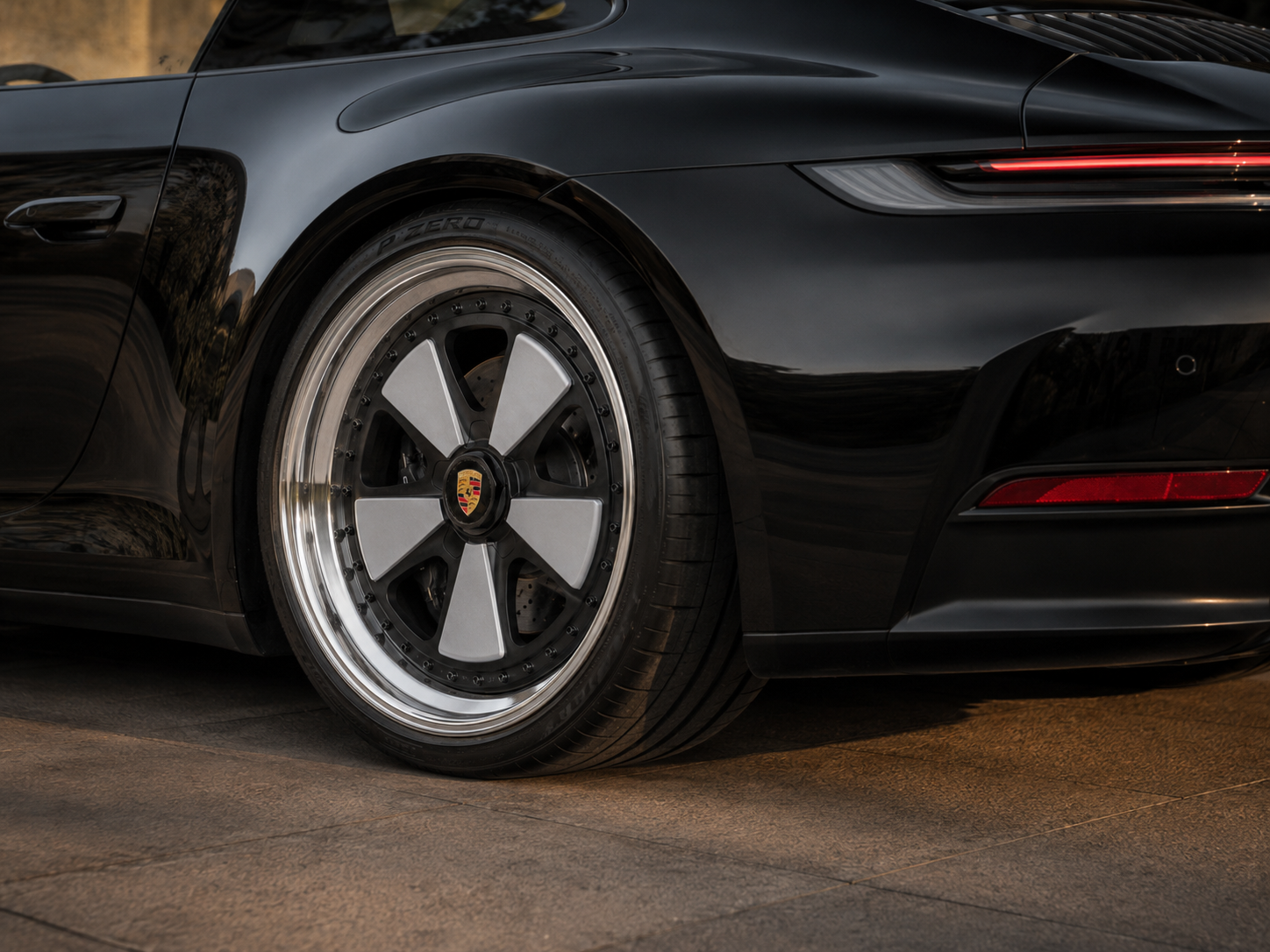
Porsche wheel arch, forged wheel outer lip alignment, and brake assembly packaging reference
Application-Specific Geometry: Every GTRS fitment specification evaluates diameter, width, offset, hub mounting, brake envelope and fender relationship for the specific Porsche generation and version.

01 / TECHNICAL SYSTEM

What Fitment Defines

Fitment determines how the wheel positions relative to the hub, brakes, suspension and body. Diameter, width, offset, mounting and tire specification must be reviewed as one technical system.

PARAMETER 01 RADIAL ENVELOPE

Diameter

Defines the nominal bead-seat diameter of the wheel in relation to brake rotor size, caliper radial clearance, tire sidewall profile and chassis proportion.
PARAMETER 02 SECTION SUPPORT

Width

Establishes the distance between the inner and outer tire bead seats, directly governing tire shoulder posture, inner barrel span and outer lip reach.

PARAMETER 03 AXIAL DATUM

Offset / ET

Locates the wheel mounting pad relative to the rim centerline, controlling how total wheel width is distributed between the inner suspension side and outer fender arch.

PARAMETER 04 HUB INTERFACE

Mounting

Matches the wheel center bore and attachment geometry to the vehicle hub—whether exposed five-lug, five-lug with center-lock-style cover, or genuine Porsche Center Lock.

PARAMETER 05 CHASSIS SIDE

Inner Clearance

Maintains required working space between the inner barrel, spoke backpad and the brake caliper, upright, damper assembly, control arms and inner wheel house.

PARAMETER 06 BODY SIDE

Outer Position

Defines how the outer wheel flange and tire sidewall align with the front and rear fender arches at static ride height and through suspension compression.

02 / GEOMETRIC PARAMETERS

Wheel Dimensions

Core wheel geometry is expressed through nominal diameter, rim width, mounting offset and axle-specific front and rear proportions.

01

DIAMETER

INCHES (″)

The nominal wheel diameter selected for the vehicle application.

Measured across the tire bead seats. Diameter selection must respect the brake rotor and caliper envelope as well as compatible front and rear tire rolling circumferences.

02

WIDTH

INCHES (J)

The wheel width, expressed in inches, which influences tire compatibility, inner clearance and outer position.

Measured internally between the tire bead flanges. Changing rim width alters both the inner barrel boundary and the outer lip position even when offset remains constant.

03

OFFSET / ET

MILLIMETERS (mm)

The position of the wheel mounting surface relative to the wheel centerline.

A lower ET value moves the wheel assembly further outward toward the fender; a higher ET value positions the wheel further inward toward the suspension. Exact ET values depend on the specific vehicle and wheel width.

04

FRONT AND REAR SPECIFICATION

STAGGERED AXLES

Porsche applications may use different front and rear dimensions.

Front and rear axles differ in track width, steering geometry, hub carrier design, brake size and arch volume, requiring independent front and rear width, diameter and offset verification.

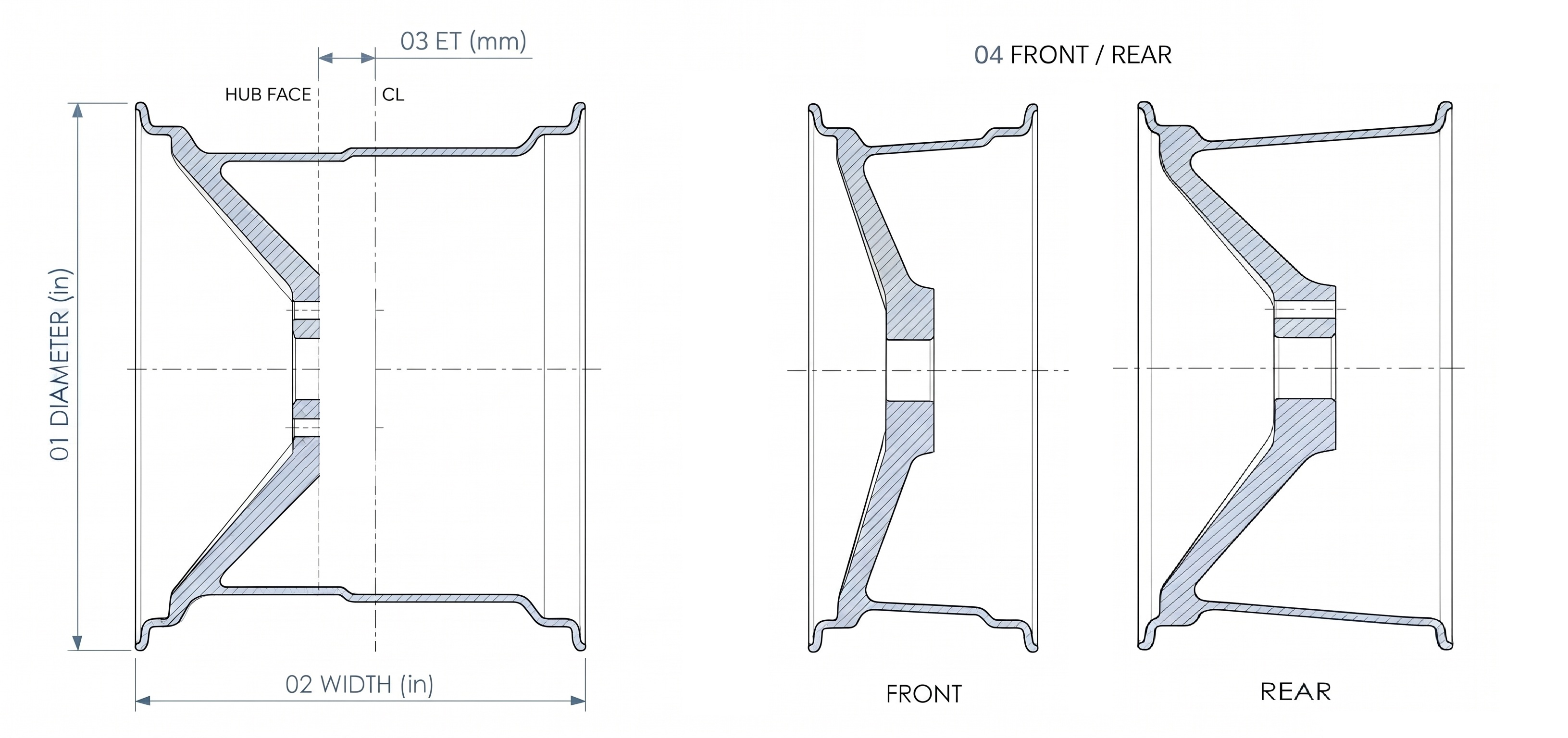
CONCEPTUAL WHEEL DIMENSIONS SCHEMATIC CROSS-SECTION GEOMETRY · NOT TO SCALE
Conceptual wheel cross-sections illustrating diameter, width, offset and front and rear wheel proportions

Illustrative example · Open full-size image

Conceptual Dimension Relationship: Diameter and Width define the rim envelope between the tire bead seats, while Offset / ET locates the hub mounting surface relative to the wheel centerline. Front and rear axles are specified independently where the Porsche platform uses staggered geometry.

03 / STANCE & POSITIONING

Fitment Presets

The GTRS Configurator provides four positioning paths depending on whether you prefer factory-reference geometry, a measured outward refinement, or an individually engineered specification.

PRESET 01 FACTORY DATUM

OEM

Uses the verified factory reference position and supported dimensions for the selected vehicle.

Retains documented original wheel positioning where a verified Porsche reference exists for the selected generation, version and wheel size.

PRESET 02 REFINED STANCE

GTRS OEM+

A subtle outward position relative to the factory reference, remaining close to the original stance where supported.

Developed around the verified vehicle reference for owners seeking a fuller arch relationship while preserving restrained factory-inspired proportions.

PRESET 03 NEAR-FENDER

GTRS FLUSH

A near-fender position developed for the verified vehicle application and selected wheel/tire configuration.

Aligns the wheel and tire assembly closer to the outer arch edge on supported references; final clearance remains dependent on tire profile, suspension and vehicle condition.

PRESET 04 BESPOKE ET

CUSTOM

An individually reviewed fitment for modified, non-standard or measurement-based applications.

Allows specific front and rear offset targets or an engineering recommendation reviewed against your vehicle’s geometry before production.

Vehicle-Specific Calculation Policy: Exact offset adjustments and ET values remain dynamic and vehicle-specific in the GTRS Configurator. Final clearance depends on the exact Porsche generation, version, wheel width, tire specification, brake package, factory spacers where applicable, and suspension setup.

04 / SPATIAL ENVELOPE

Inner and Outer Clearance

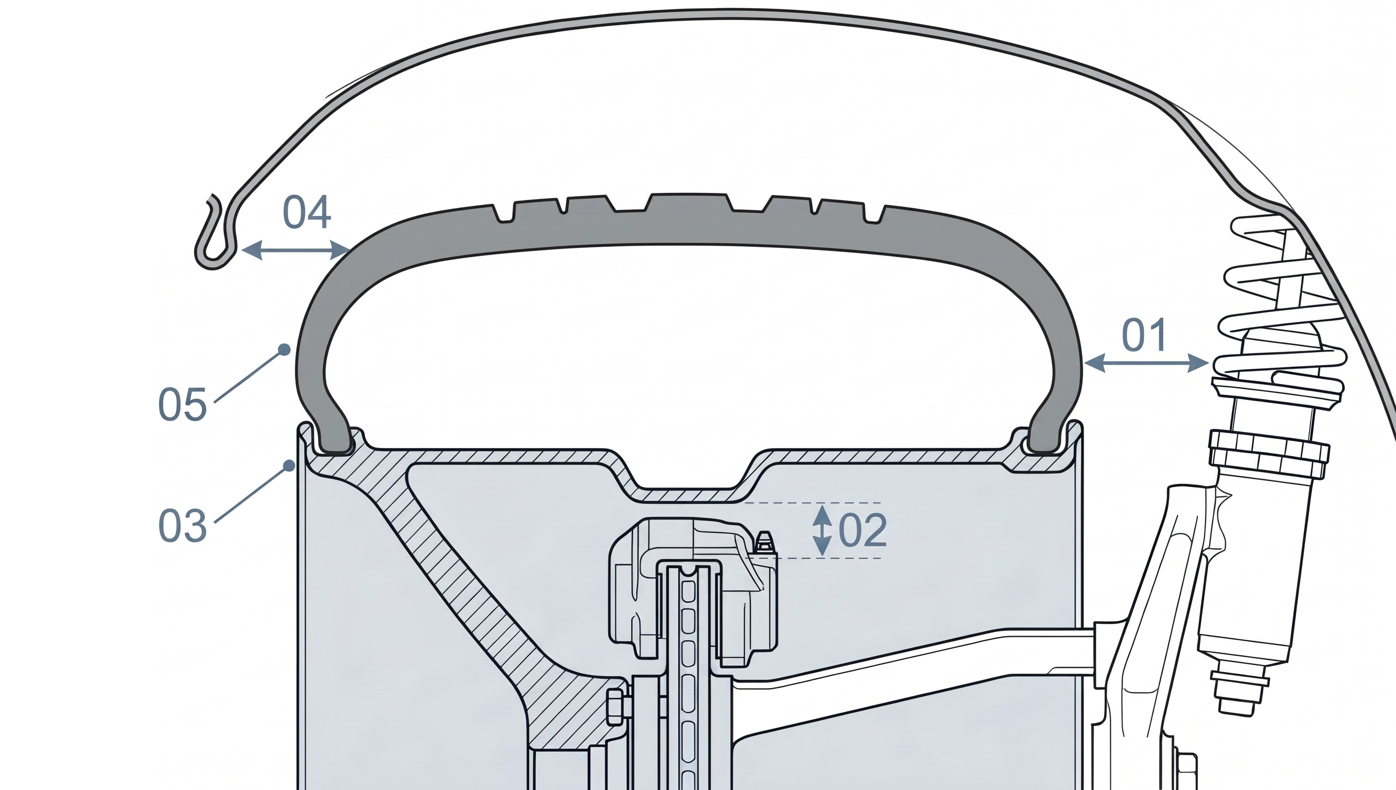
Moving a wheel outward can increase inner clearance while reducing available space toward the fender. Wheel width and offset must be considered together.

INNER & OUTER CLEARANCE ENVELOPE WIDTH + OFFSET INTERACTION · NOT TO SCALE
Conceptual wheel, tire, brake and suspension cross-section with five clearance reference markers

Illustrative example · Open full-size image

Coupled Clearance System: Outward offset reduces the distance to the outer fender arch while increasing space on the suspension side; wider rims expand both boundaries simultaneously.
01

Suspension-side clearance

Available space between the inner rim flange, tire inner sidewall and the suspension upright, damper body, spring perch and control-arm links.

02

Inner barrel clearance

Radial and axial working space inside the wheel barrel around the brake caliper housing, rotor hat, steering tie-rod ends and axle hardware.

03

Outer lip position

Lateral placement of the outer wheel flange determined by the combination of rim width and offset relative to the vehicle hub face.

04

Fender relationship

Alignment between the wheel assembly and the outer fender arch lip and inner arch liner under static load, steering articulation and suspension compression.

05

Tire sidewall position

Tire section width, aspect ratio and shoulder contour mounted on the chosen rim width, which establish the true outer envelope near the bodywork.

05 / CALIPER & BARREL PACKAGING

Brake Clearance

Brake clearance depends on the caliper envelope, wheel diameter, inner barrel geometry, mounting architecture and spoke profile.

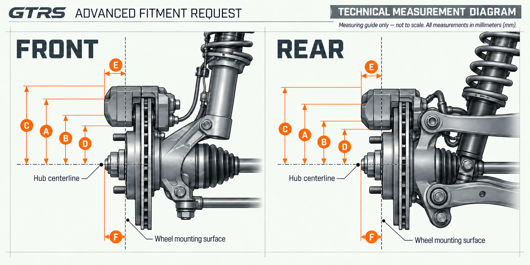
APPROVED GTRS FRONT & REAR MEASUREMENT REFERENCE HUB CENTERLINE (A–D) · MOUNTING SURFACE (E–F) · ALL VALUES IN MM
GTRS front and rear brake caliper, hub centerline, and wheel mounting surface technical diagram showing reference dimensions A through F in millimeters
Front & Rear Brake Envelope Reference: Dimensions A–D locate the brake caliper profile from the horizontal hub centerline; dimensions E and F measure caliper and drive-shaft protrusion beyond the wheel mounting surface. Measuring guide only — not a scale drawing.
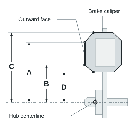
RADIAL CLEARANCE DATUMS (A–D) HUB CENTERLINE REFERENCE
Orthographic diagram showing radial distances A, B, C, and D from the hub centerline to the brake caliper outward face and overall top and bottom edges
A–D / From the Hub Centerline: A and B locate the far and near edges of the outward-facing caliper face; C and D locate the overall top and bottom of the caliper.
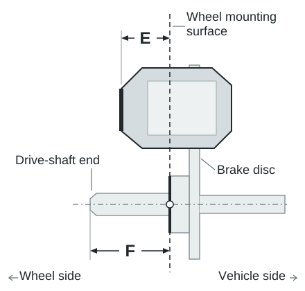
AXIAL PROTRUSION DATUMS (E–F) MOUNTING SURFACE REFERENCE
Orthographic diagram showing axial protrusion E for the brake caliper and F for the drive-shaft beyond the wheel mounting surface
E–F / Beyond the Mounting Surface: E measures caliper protrusion and F measures drive-shaft protrusion relative to the same wheel mounting surface.
01

Caliper radial clearance

Evaluates caliper height from the hub centerline against the internal barrel step and drop-center contour.

02

Caliper axial clearance

Reviews outward caliper overhang beyond the wheel mounting surface relative to the spoke backpad plane.

03

Spoke-to-caliper relationship

Shapes the inner spoke sweep and backpad relief around the outward-facing caliper profile on each axle.

04

Inner barrel relationship

Coordinates barrel diameter and internal profile with iron, surface-coated, ceramic-composite (PCCB) or aftermarket brake hardware.

05

Mounting-plane position

Coordinates hub-pad depth, drive-shaft protrusion and offset so spoke concavity is developed within the verified brake-clearance envelope.

Concavity & Brake Envelope Boundary: Available concavity and wheel face profile depend on the specific vehicle, axle width, offset and brake package; the same concavity depth or wheel face does not clear every brake package.

06 / HUB INTERFACE

Mounting Options

GTRS supports three mounting configurations, selected to match the vehicle’s hub architecture.

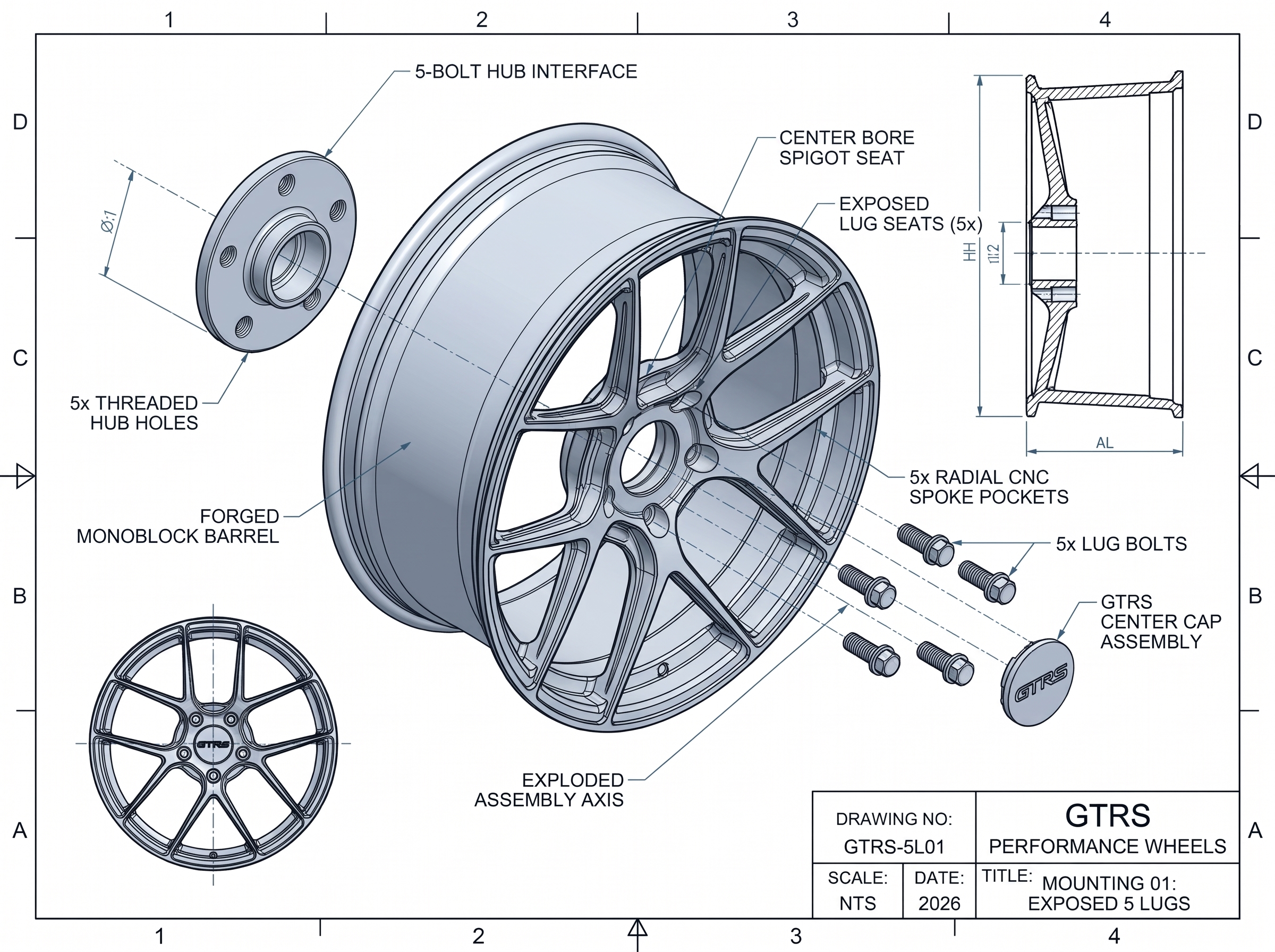
MOUNTING 01 5-BOLT HUB

EXPOSED 5 LUGS

Illustrative exploded view of exposed five-lug wheel mounting and center cap

Illustrative example · Open full-size image

Standard exposed five-lug mounting where supported.

Machined for the vehicle’s five-bolt pattern and center bore with exposed lug seats and a GTRS center cap assembly.

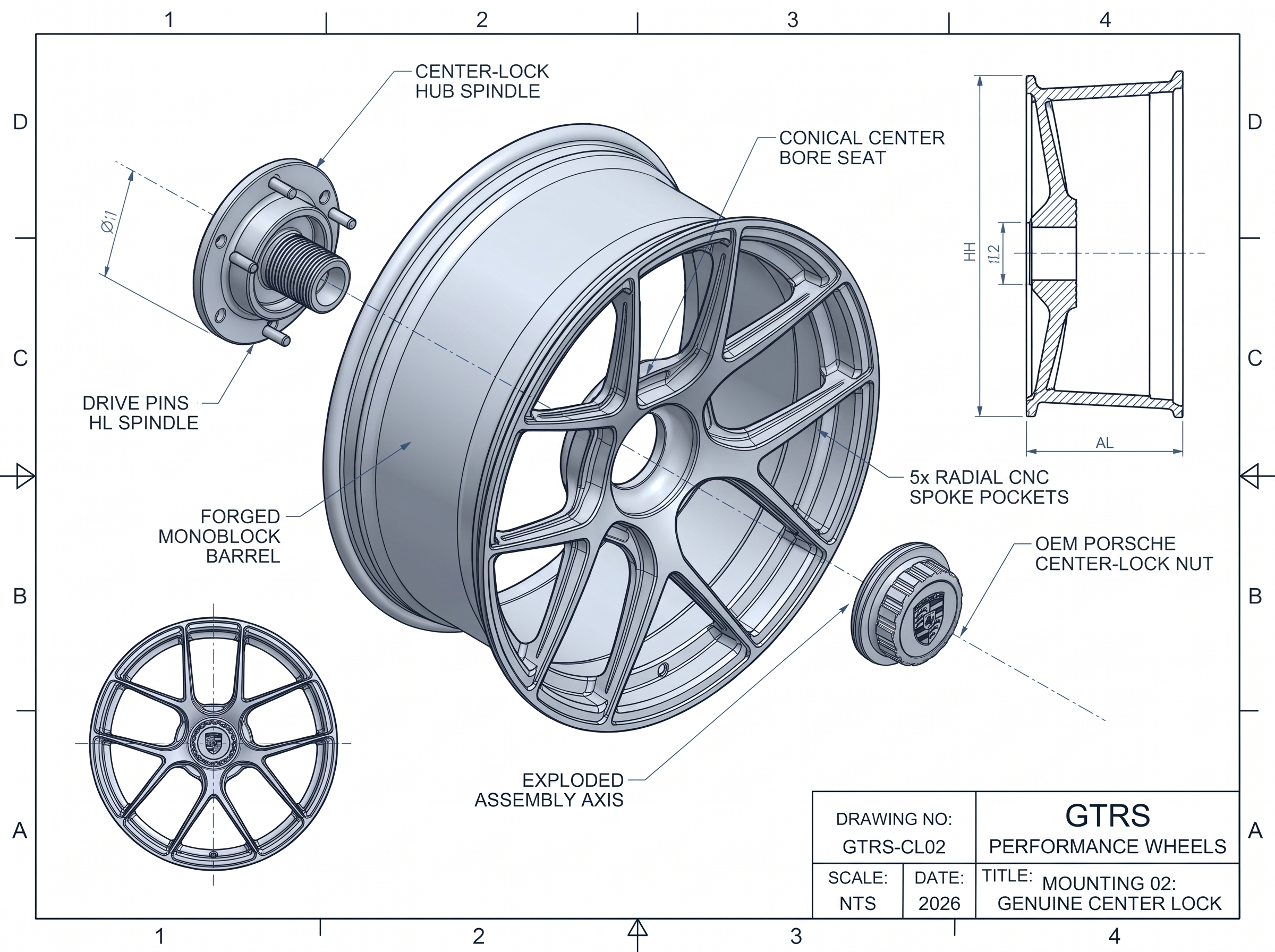
MOUNTING 02 CENTER-LOCK HUB

GENUINE CENTER LOCK

Illustrative exploded view of a genuine center-lock wheel and hub interface

Illustrative example · Open full-size image

Real Porsche Center Lock configuration where the vehicle hub and wheel model are verified as eligible.

Engineered exclusively for Porsche models equipped with a genuine factory or verified Center Lock hub interface and compatible wheel center geometry.

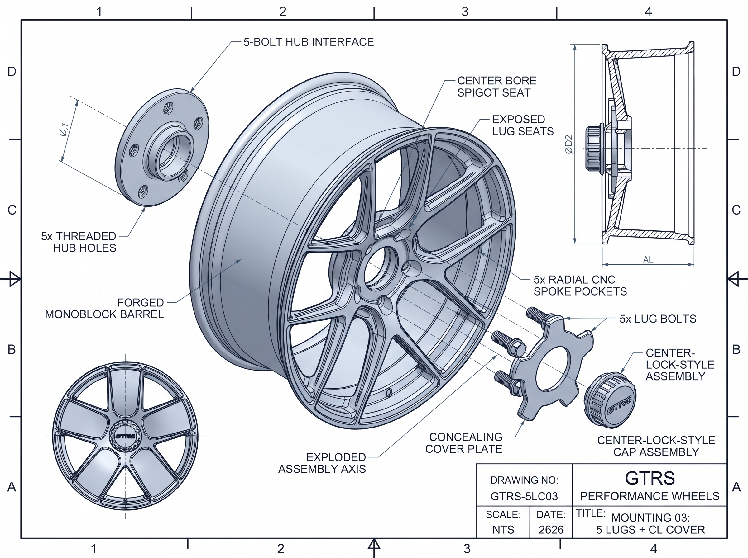
MOUNTING 03 5-BOLT + COVER

5 LUGS WITH CENTER-LOCK-STYLE COVER

Illustrative exploded view of five-lug wheel mounting with a decorative center-lock-style cover

Illustrative example · Open full-size image

Five-lug mounting with a center-lock-style cover, available across all GTRS wheel models.

A core focus of the GTRS range, this design retains the underlying five-bolt wheel attachment beneath a center-lock-inspired cover.

Mounting Compatibility: Genuine Center Lock requires a compatible Center Lock hub and verified wheel specification. The center-lock-style cover is available across all GTRS wheel models and retains the vehicle’s five-lug mounting system.

SEE THE ASSEMBLY

Center-Lock-Style Cover — Installation Examples

Three wheel designs, three cover assemblies, one clean center-lock-style result. See how each model-specific cover fits over the wheel’s five-lug mounting area.

The wheel retains its five-lug attachment to the vehicle. These videos demonstrate the cover assembly; use the installation instructions supplied with your wheel set.

07 / NON-FACTORY VARIABLES

Vehicle Modifications

Suspension, brake and body modifications can change the available wheel position and clearance.

01

Lowered suspension

Alters static ride height, dynamic camber curve and available outer arch clearance under compression.

02

Coilovers

Spring perches, helper springs and damper body diameter can change inner wheel-to-strut clearance.

03

Air suspension

Requires reviewing both normal driving ride height and aired-out lip-to-fender positioning.

04

Aftermarket brakes

Big-brake kits, larger rotors and multi-piston calipers alter the radial and axial A–F brake envelope.

05

Wider fenders or bodywork

Widebody conversions, flared arches or rolled lips shift the usable outer bodywork boundary.

06

Wheel spacers

Factory or aftermarket hub spacers change effective installed wheel position relative to stamped wheel ET.

07

Non-standard tires

Wider tread sections, track compounds or altered aspect ratios change shoulder profile and arch clearance.

08

Track alignment settings

Increased negative camber, caster adjustments and track-width shims reposition the upper tire shoulder and inner barrel.

Not every modification requires the same measurement procedure; GTRS reviews the project details first and confirms which specific dimensions or photographs are needed.

08 / BESPOKE TECHNICAL INTAKE

When Advanced Fitment Is Required

Use Advanced Fitment when standard factory vehicle references are not sufficient to define your wheel specification.

USE ADVANCED FITMENT WHEN:

  1. 01 The vehicle has non-standard brakes
  2. 02 Suspension geometry has changed
  3. 03 The body or fenders are modified
  4. 04 Current wheel/tire dimensions differ substantially from the factory reference
  5. 05 Additional lip depth or concavity is requested
  6. 06 The verified GTRS reference does not fully describe the application
  7. 07 The project requires direct measurements

09 / CONFIRMATION WORKFLOW

How Fitment Is Confirmed

Every GTRS wheel set passes through a structured four-stage review before manufacturing release.

  1. STAGE 01 PLATFORM

    01 — Vehicle Identification

    Generation, version and relevant equipment are identified.

  2. STAGE 02 BASELINE

    02 — Reference Review

    Current dimensions and verified GTRS data are reviewed.

  3. STAGE 03 VERIFICATION

    03 — Measurements Where Required

    Advanced Fitment measurements and photographs are used for modified or non-standard applications.

  4. STAGE 04 CONFIRMATION

    04 — Final Specification

    The approved wheel dimensions, ET, mounting and fitment preset are confirmed before production.

Production Release Policy: Fitment approval is an explicit engineering confirmation completed prior to manufacturing; price estimation or checkout payment alone does not constitute technical fitment approval.

PORSCHE CONFIGURATOR

Configure Your Porsche Fitment

Select your Porsche generation and version to review supported wheel diameters, widths, OEM / GTRS OEM+ / GTRS Flush / Custom presets, mounting options and finishes.

TECHNICAL CONSULTATION

Discuss a Specific Application

Planning a modified Porsche project, aftermarket brake upgrade or bespoke wheel specification? Start an Advanced Fitment intake or contact GTRS directly.