
Aftermarket brake system
Big-brake kits, multi-piston calipers or non-factory rotor bells requiring A–F envelope verification.
Advanced Fitment is used when factory references are not sufficient to confirm the required wheel position, brake clearance, concavity or custom body relationship.
You do not need to know your wheel specifications to begin. Share your project and the information you already have—GTRS confirms which measurements are required for the specific application.
01 / APPLICATION SCOPE
Modified vehicles, brake upgrades and custom wheel proportion targets alter the physical relationship between the hub, caliper, suspension and bodywork.
Big-brake kits, multi-piston calipers or non-factory rotor bells requiring A–F envelope verification.
Coilovers, adjustable control arms, motorsport uprights or custom track-width and camber settings.
Front and rear quarter-panel extensions or bespoke body kits requiring non-standard widths and offsets.
Rolled, flared or reshaped wheel arches that change the outer lip and tire shoulder boundary.
Variable ride-height systems where both driving stance and compressed arch clearance must be coordinated.
Custom diameter combinations, wider rim sections or non-OEM tire profiles outside documented factory tables.
Projects prioritizing the deepest feasible spoke profile permitted by the axle width, offset and caliper overhang.
Monoblock Deep Lip or Two-Piece Duo-Block specifications tailored around outer rim step and brake clearance.
Center-lock hub conversions, motorsport hubs or special drive-shaft protrusion verification.
Heritage 911, 930, 964 or 993 builds combining classic bodywork with updated brakes, hubs or suspension.
02 / INTAKE SPECIFICATION
To begin, only your contact details, vehicle identification and a short project description are mandatory. Additional technical details can be supplied where known.
Make, model, chassis generation and variant (for example 992 GT3, 991.2 Turbo S, 964 Carrera 2 or restomod base).
Entered alongside vehicle identification so market-specific hub, spacer or brake revisions can be checked.
Factory iron, surface-coated, PCCB or aftermarket brake system, caliper model, disc diameter and any mounting-bracket changes.
Existing front and rear wheel diameters, rim widths and stamped offsets (ET) currently installed on the vehicle.
Installed or planned front and rear tire sizes and any rubbing or clearance observations during steering or compression.
Lowering springs, coilover system, air suspension, ride-height adjustment and front/rear camber settings.
Widebody conversion kit, flared fenders, rolled arch lips and approximate front/rear width extension.
Thickness of any factory or aftermarket wheel spacers on the front and rear axles, and whether you plan to retain or remove them.
Design direction—OEM-inspired positioning, flush stance, maximum feasible concavity, deep lip, or track-focused geometry.
Five-lug, genuine Porsche Center Lock, or modified hub architecture, plus bolt pattern and center bore if non-standard.
Your desired visual and functional outcome, preferred GTRS wheel design, finish direction, and any workshop measurement notes.
03 / APPROVED ENGINEERING PLATE
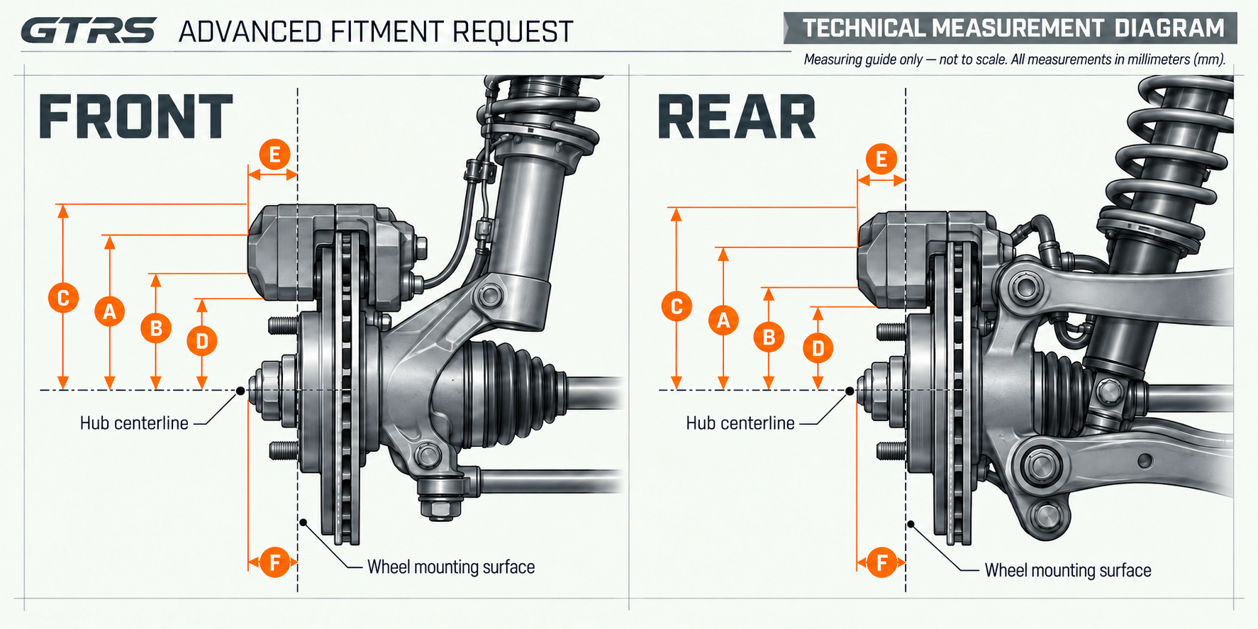
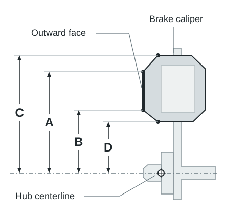
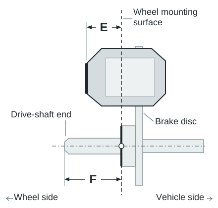
The approved GTRS Front & Rear measurement reference defines six brake and hub dimensions (A–F) in millimeters, recorded separately for the front and rear axles.
Measure each axle separately. Use the labeled references below, then enter your front and rear A–F measurements.
Open full-size diagram (opens in a new tab)
A–D / From the hub centerline A and B locate the far and near edges of the outward-facing caliper face. C and D locate the overall top and bottom of the caliper.
E–F / Beyond the mounting surface E measures caliper protrusion. F measures drive-shaft protrusion. Both use the same wheel mounting surface.
| Label | Reference Datum | Approved GTRS Definition | Axle Fields |
|---|---|---|---|
| A | Hub centerline (radial) | Distance from the hub center to the far edge of the outward-facing caliper face. | front_a / rear_a (mm) |
| B | Hub centerline (radial) | Distance from the hub center to the near edge of the outward-facing caliper face. | front_b / rear_b (mm) |
| C | Hub centerline (radial) | Distance from the hub center to the top edge of the caliper. | front_c / rear_c (mm) |
| D | Hub centerline (radial) | Distance from the hub center to the bottom edge of the caliper. | front_d / rear_d (mm) |
| E | Wheel mounting surface (axial protrusion) | Caliper protrusion beyond the wheel mounting surface. | front_e / rear_e (mm) |
| F | Wheel mounting surface (axial protrusion) | Drive-shaft protrusion beyond the wheel mounting surface. | front_f / rear_f (mm) |
04 / WORKSHOP PROCEDURE
Follow the approved GTRS workshop measurement guidelines when recording front and rear A–F dimensions or documenting vehicle stance.
Ensure the vehicle rests on a flat, level surface before evaluating ride height, arch posture or suspension geometry.
Record all A–F values in millimeters (mm). Use a decimal point or comma, such as 12.5 or 12,5.
Where direct measurements are taken, capture a clear reference photo showing the ruler, depth gauge or caliper against the datum.
Front and rear brake calipers and hubs differ in size and overhang; record Front axle and Rear axle values separately.
Record any left-to-right bodywork variation, camber difference or arch modification in the workshop measurement notes.
Indicate whether factory or aftermarket wheel spacers are fitted and whether measurements were taken with the mounting face clean.
Document whether the vehicle is at stock height, lowered coilover height, or a specific air-suspension ride mode.
Leave unknown values blank; a genuine zero stays zero. Never substitute rotor diameter, offset or fender clearance for A–F.
05 / VISUAL DOCUMENTATION
Clear reference photographs help GTRS verify arch alignment, brake packaging, installed wheel markings and measurement tool placement.
Complete vehicle profile on a level surface showing overall stance, ride height and front-to-rear wheel balance.
Angled front view illustrating how the front wheel and tire sit relative to the front fender arch and bumper line.
Angled rear view showing rear quarter-panel width, arch lip contour and rear wheel stance.
Sightline view along the body side showing outer rim flange and tire sidewall position relative to the fender edge.
Clear view of the front and rear brake calipers, rotor bells and available space behind the wheel spokes and barrel.
Stamped or engraved width, diameter, offset (ET) and part markings on the existing front and rear wheels.
Sidewall markings showing tire width, aspect ratio, diameter and model on both axles.
Visible five-lug, cover or center-lock hub hardware and any installed spacer markings where accessible without disassembly.
Workshop photographs showing the measuring scale or caliper in position so the reference point can be verified.
06 / TECHNICAL CONSULTATION
Contact GTRS with your vehicle details, photographs and available measurements to begin the technical review.
The online measurement submission workflow is not currently enabled for public use.
07 / ENGINEERING EVALUATION
Each Advanced Fitment request is reviewed individually by GTRS before a manufacturing specification is confirmed.
Vehicle information, measurements and images are reviewed.
Fitment, mounting, brake and body relationships are assessed.
GTRS may request a missing measurement or clearer photograph.
The approved wheel configuration can proceed to final order review.
08 / SPECIFICATION HANDOFF
Once the application is confirmed, the verified dimensions, offset, mounting and fitment position are used to complete the GTRS configuration.
Already know your specifications? Continue directly through the Porsche Configurator, including Custom options. This consultation is not an additional checkout requirement.
PORSCHE CONFIGURATOR
Explore verified Porsche fitments, Custom ET options, forged constructions and finishes in the GTRS Configurator, or review the Fitment Guide.
DIRECT CONSULTATION
Have questions for GTRS engineering or your installation workshop before taking measurements? Contact GTRS directly.