
Diameter
Nominal wheel diameter at the tire bead seat, selected around brake rotor packaging, tire availability and Porsche chassis proportion.
GTRS ENGINEERING
Every GTRS wheel project is developed around the vehicle, the selected design architecture and the intended fitment. Engineering defines the geometry before manufacturing begins.
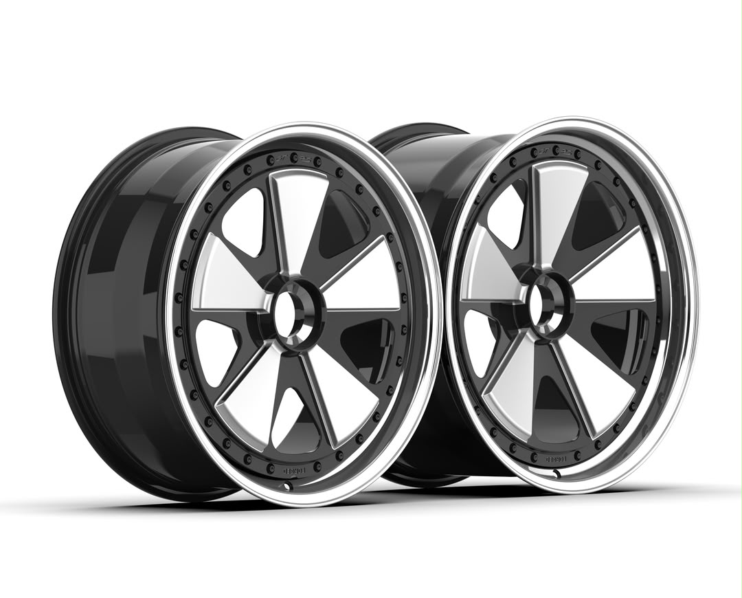
01 / ENGINEERING WORKFLOW
The engineering scope depends on the wheel model, vehicle application and requested configuration. Established specifications use verified GTRS data, while custom applications may require additional review.
Review of the exact Porsche generation, version, brake configuration, suspension setup, bodywork and intended road or track application.
Review StageDiameter, width, offset, hub mounting, inner clearance and outer position defined together as one vehicle-specific technical system.
Review Stage3D CAD definition of center architecture, spoke profile, concavity, mounting pad, brake clearance and construction proportions.
Review StageEvaluation of load paths, stress distribution and deformation where applicable to the selected model, construction and application.
Review StageConfirmation of the approved model code, construction, front and rear dimensions, offset, mounting and finish program before manufacturing.
Review Stage02 / STAGE 01 — APPLICATION INPUTS
The project begins with the exact Porsche generation, version and intended application. Existing wheel and tire dimensions, brake configuration, suspension and body modifications may be reviewed where relevant.
Platform architecture, track width, hub carrier geometry and axle load characteristics for the specific Porsche generation and trim.
Reference front and rear wheel diameters, rim widths, offsets, tire section widths and rolling circumference.
Factory iron, surface-coated, ceramic-composite (PCCB) or aftermarket brake calipers and rotor diameters across both axles.
Ride-height adjustments, coilover hardware, spring perches, camber settings and control-arm clearance envelopes.
Factory narrow-body, widebody or conversion arch profiles, liner clearance and outer lip positioning requirements.
Grand touring road use, mixed road and circuit days, or dedicated track tire compounds and thermal operating conditions.
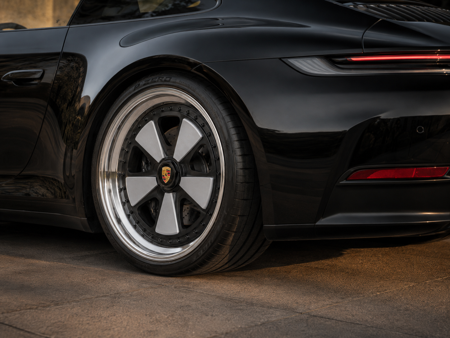
03 / STAGE 02 — GEOMETRIC PACKAGING
Fitment defines how the wheel sits relative to the hub, brake package, suspension and body. Width, diameter, offset and mounting are reviewed as one technical system.
Nominal wheel diameter at the tire bead seat, selected around brake rotor packaging, tire availability and Porsche chassis proportion.
Rim width between inner and outer bead seats, matched to the front and rear tire section width and axle track geometry.
Distance in millimeters between the wheel centerline and the hub mounting surface, governing both inner clearance and outer stance.
Vehicle-specific center bore, bolt pattern (Exposed 5 Lugs or 5 Lugs with Center Lock-Style Cover) or verified Real Center Lock hub interface.
Spatial envelope between the inner rim barrel, spoke backpad and the brake caliper, upright, suspension links and wheel house.
Alignment of the outer rim flange and tire profile relative to the fender arch across OEM, GTRS OEM+, GTRS Flush or Custom fitment targets.
04 / STAGE 03 — 3D GEOMETRY DEFINITION
The selected GTRS design is developed into a vehicle-specific wheel geometry. The CAD stage defines the center architecture, spoke profile, concavity, mounting area, rim proportions and construction details.
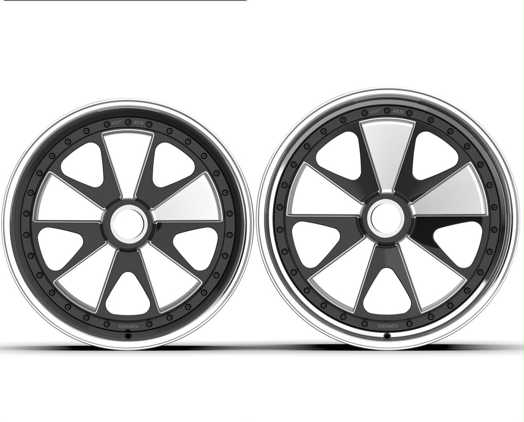
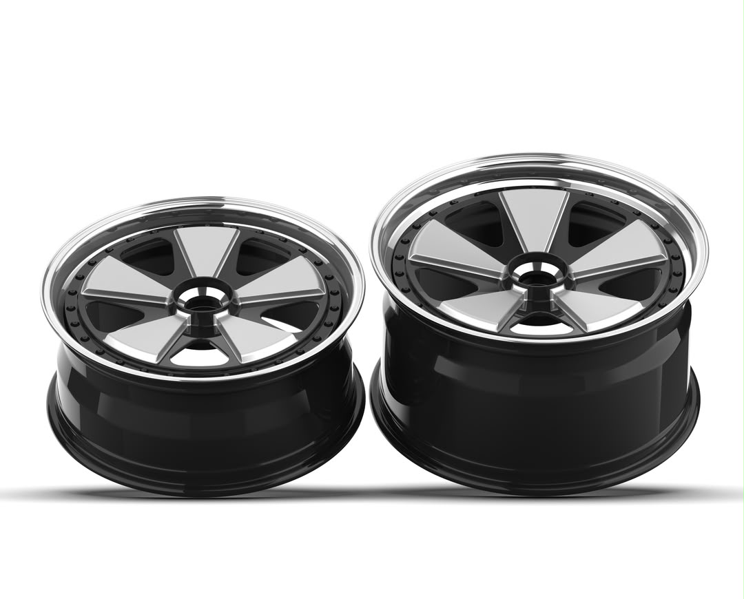
Each CAD model is parameterized for the target vehicle’s front and rear dimensions rather than scaled from a generic display model.
Spoke cross-sections, chamfers, relief pockets and center-disc transitions are modeled to preserve the design’s visual character.
Spoke curvature and center-drop depth are maximized within the available offset and brake-caliper envelope for each axle.
Hub-pad thickness, center-bore register, lug seat geometry or Center Lock interface are defined to match the vehicle hub.
Monoblock, Monoblock Deep Lip and Duo-Block architectures receive dedicated rim-lip, flange and barrel geometry in CAD.
Completed CAD assemblies define the solid geometry required for structural review and precision CNC machining.
05 / STAGE 03B — ENVELOPE VERIFICATION
Brake clearance and concavity are developed together. The available spoke depth depends on the brake package, mounting architecture, wheel dimensions and vehicle-specific clearance.
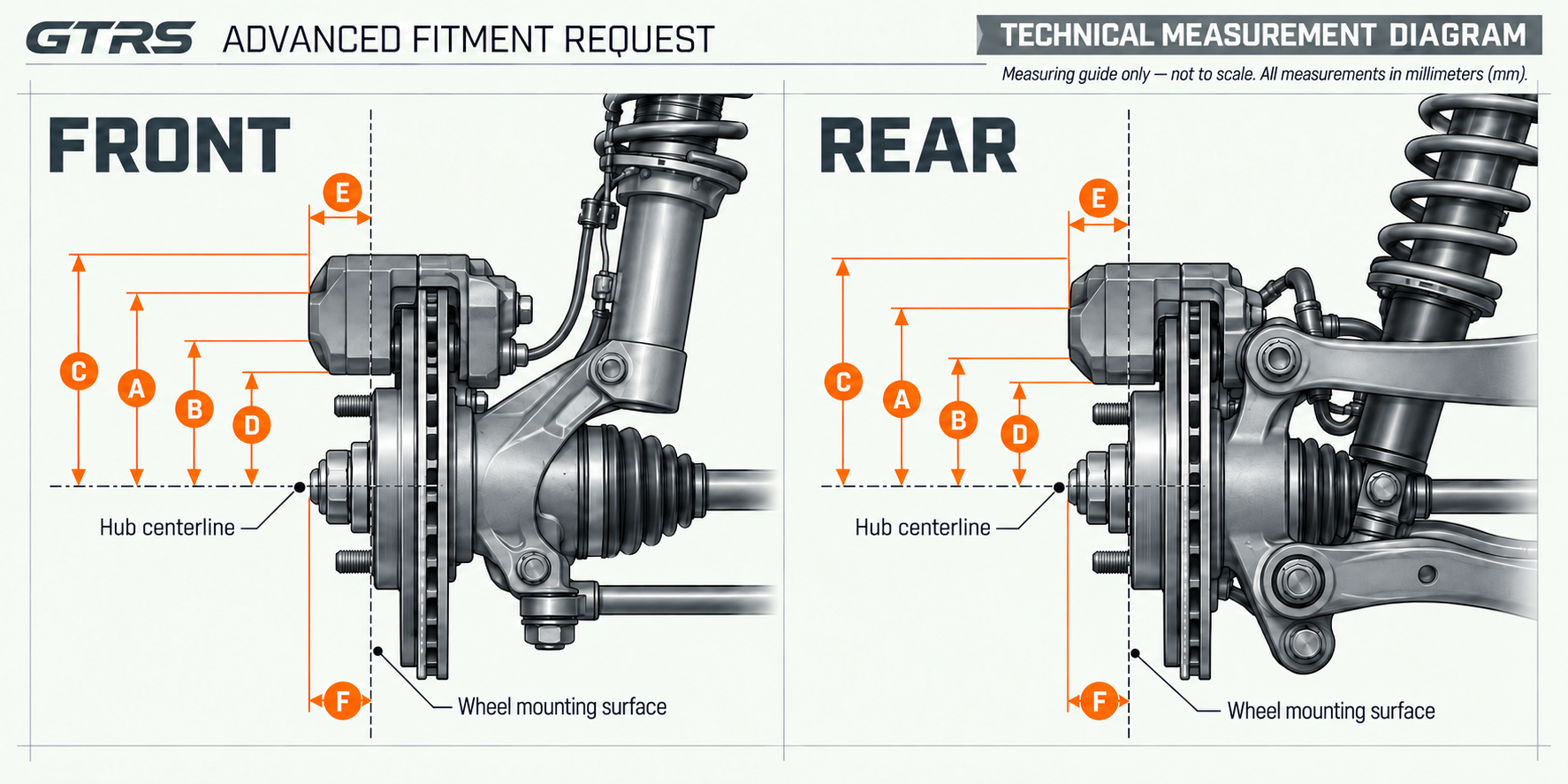
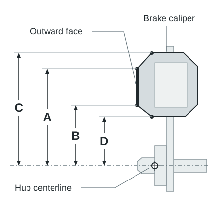
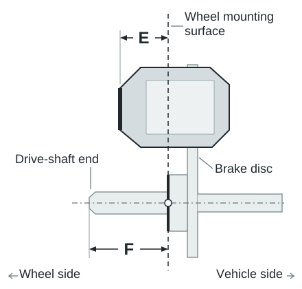
Available concavity varies by Porsche generation, axle width, offset and brake package; not every Porsche application permits the same concavity depth.
06 / STAGE 04 — STRUCTURAL REVIEW
Engineering analysis can be used to study load paths, stress distribution and deformation within the wheel geometry. The analysis scope depends on the model, construction and intended application.
Material inputs, constraints and load cases must match the relevant engineering specification before a result is presented as applicable.
Traces how radial, cornering and braking forces transfer from the tire bead seat through the rim barrel and spokes into the hub mounting pad.
Evaluates stress concentration transitions along spoke roots, window radii, pocketing transitions and the mounting flange.
Studies elastic deflection behavior under the specified load case so rim and spoke stiffness align with the intended application.
Guides targeted adjustment of spoke cross-sections, fillet radii and backpad mass allocation without compromising design intent.
Accounts for the distinct structural geometry of Monoblock, Monoblock Deep Lip and Duo-Block wheel architectures.
07 / ARCHITECTURAL APPLICATION
Each GTRS wheel construction requires specific CAD geometry, section allocation and clearance verification tailored to its structural architecture.
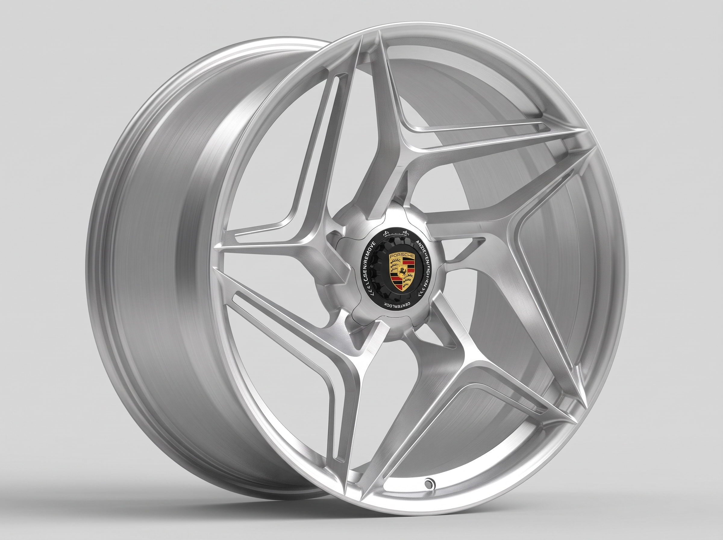
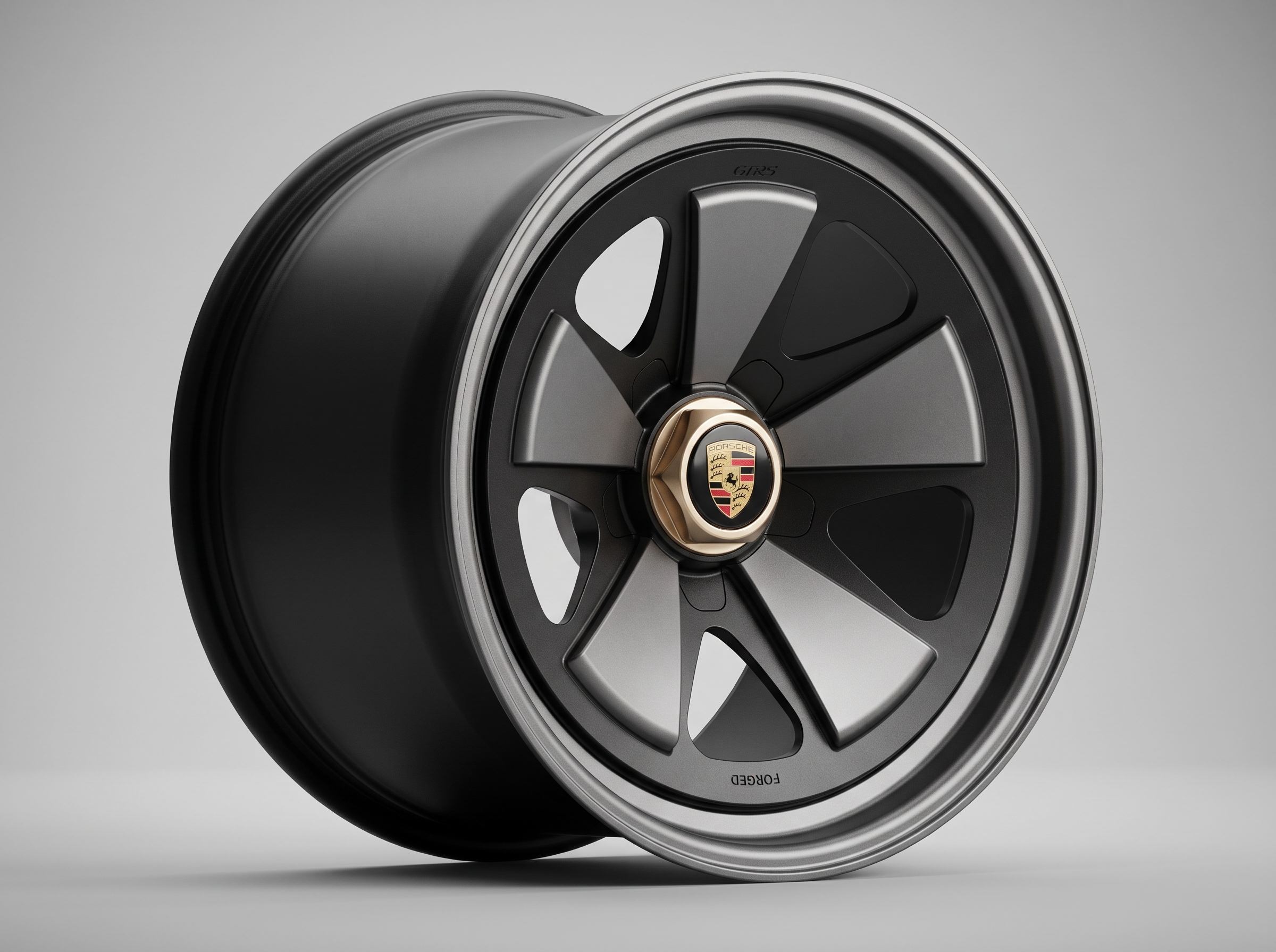
MONOBLOCK
Single-piece forged geometry with vehicle-specific center, spoke and rim architecture.
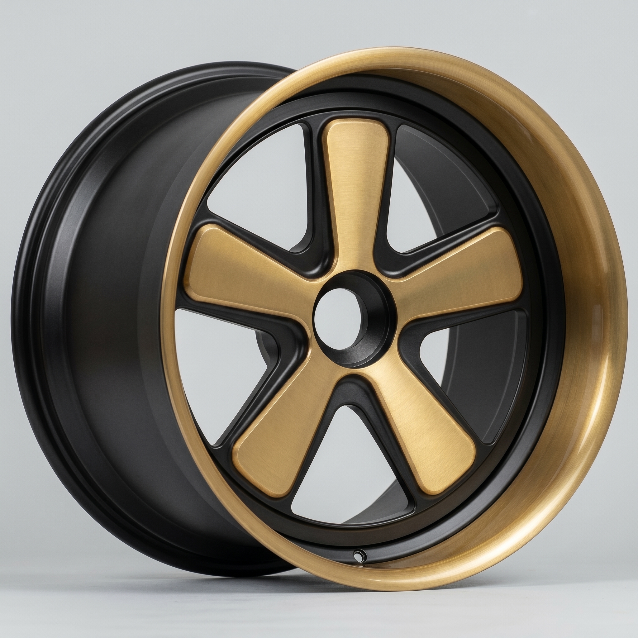
MONOBLOCK DEEP LIP
Single-piece forged geometry with integrated lip depth and construction-specific material allocation.
DUO-BLOCK
Separate face and barrel architecture requiring construction-specific face, barrel and interface definition.
08 / STAGE 05 — TECHNICAL RELEASE
The final specification defines the approved wheel model, construction, dimensions, offset, mounting and finish program for the intended vehicle application.
09 / TECHNICAL RECORDS & REPORTS
Finite Element Analysis (FEA) load validation and model-specific technical documentation are available on request for your Porsche specification.
JWL / VIA and other technical documents apply by wheel model where documented.
Prepared on request where available for the relevant wheel model, construction and vehicle application. Confirm availability and scope with GTRS when specifying your project.
JWL / VIA and other technical documents apply by wheel model where documented. Documentation scope is model-specific; no single document covers every wheel or every country’s local road-approval requirements.
10 / MANUFACTURING & INSPECTION HANDOFF
Once the technical specification is confirmed, the project continues through manufacturing and final quality-control review. Fitment, finish and visible condition are checked before packing.
Quality-control photos or video of the completed wheel set are provided before shipment.
Approved model, dimensions, offset, mounting and finish program transfer directly to forged production and CNC machining.
Completed wheel sets undergo quality-control review checking fitment parameters, surface finish and visible condition prior to packing.
Quality-control photos or video of the completed wheel set are provided before dispatch.
11 / PORSCHE CONFIGURATOR
Select a GTRS design and configure the vehicle, fitment, construction, mounting and finish.
12 / TECHNICAL CONSULTATION
Contact GTRS for guidance on vehicle fitment, brake clearance, construction and engineering documentation.